
Manual
How do I connect everything?
In the following chapters you will find explanations and pictures on how to connect LED strips and related products in different combinations.
Table of contents
1.1 Connecting to a power supply
1.2 Connecting to a power supply and an LED Dimmer
1.2.1 LED Dimmer with remote control
2.1 How to connect?
2.1.1 Connecting the RGB LED strip to the RGB controller
2.1.2 Connecting the RGB controller to the power supply
1 Single color LED Strip
1.1 Connecting to a power supply
If you order a length of LED strip with only a power supply, you will receive the following:
1) LED Strip of certain length
2) Power supply
3) Connector cable power supply - LED strip
4) Power cord*
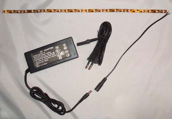
*(Not applicable for Power supply 12 Watt)
To make the LED strip light up, the following connections need to be made:
1) Connect the power cord to the power supply.*
2) Connect the LED strip connector cable to the power supply.
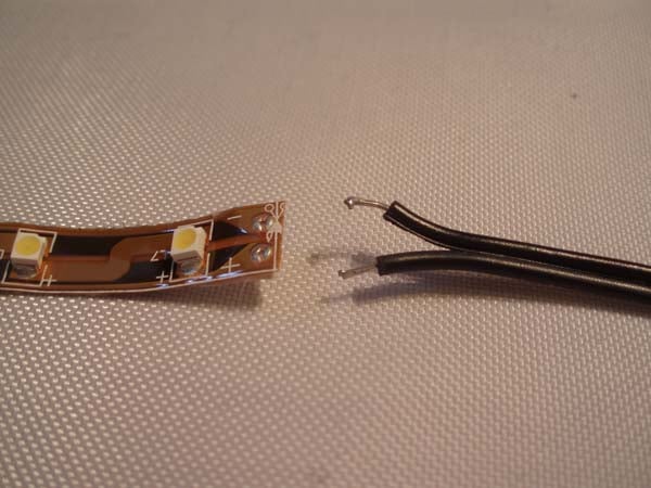
3) Solder the LED strip connector cable onto the LED strip. (For a soldering guide, go to chapter 3, or let us do the soldering work for you). It is important to connect the + and - wire properly. The connector cable has two wires. Look for a grey uninterrupted line, this is the + wire. It is also possible that one of the wires has an interrupted white line on it. This is the - wire.
+ and - are also indicated on the LED strip.
1.2 Connecting to a power supply and an LED dimmer.
If you also order a dimmer, you will receive the following:
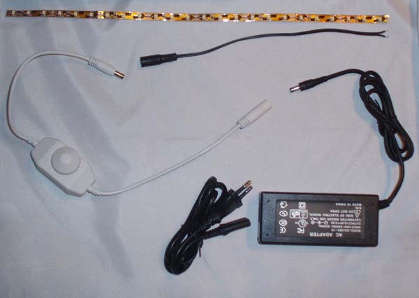
This is mostly the same as in 1.1. The LED dimmer must be connected between the power supply and the LED strip.
1.2.1 LED Dimmer with remote control
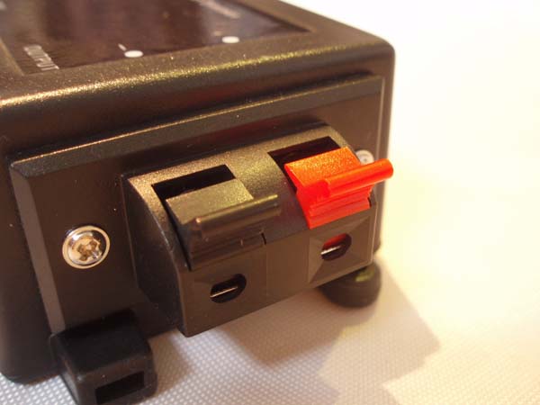
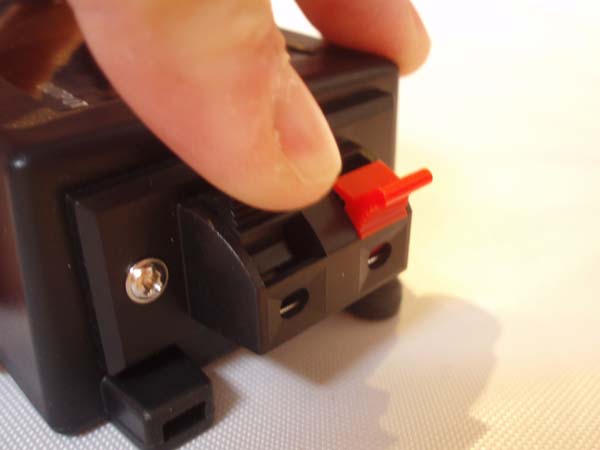
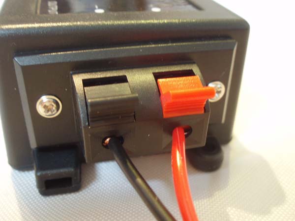
The LED Dimmer with remote does not come with connectors. Instead, the wires need to be stripped and connected to the inputs of the LED dimmer individually. It is important that the wires are connected correctly: the dimmer has an input (power supply) and an output (LED strip). If you connect them the wrong way around, the dimmer will not work.
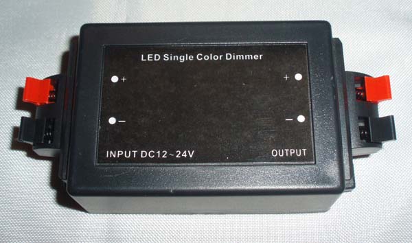
You can connect wires to the dimmer as follows:
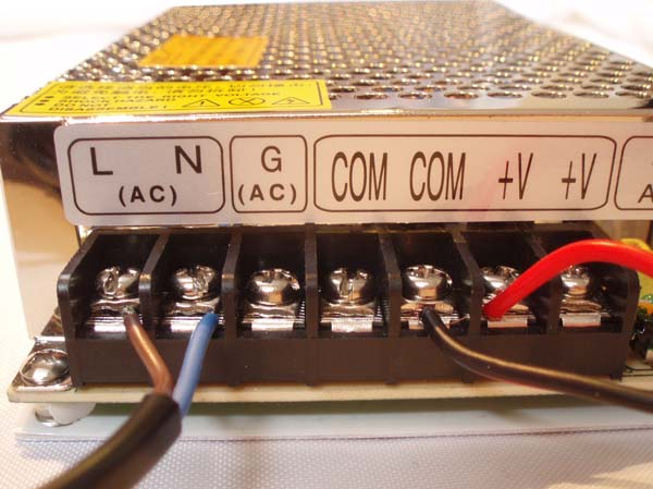
1.3 Open Frame Power supplies
Larger power supplies, Power supply 100 Watt or Power supply 150 Watt, have separate inputs and outputs. The electrical cord must be connected to this power supply manually. This is done by loosening the screws on the input, putting the stripped wire inside and fastening the screw again. This is not hard, but make sure that connections are made properly.
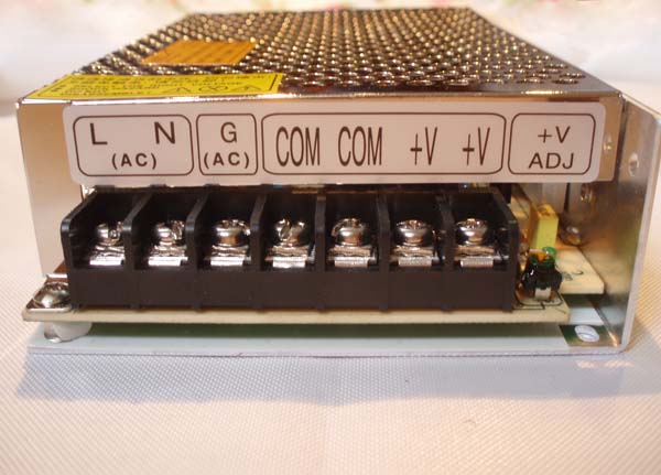
“L” and “N” are the inputs, the wires of the 100-230V electrical cord are connected here. The cord usually has a blue and a brown wire. In which order they are connected is not important, because we are dealing with alternating current. (AC)
If you have a grounded electrical cord, the G(AC) is connected to the ground wire, which is usually green.
COM and V+ are the 12V outputs of the power supply. These are connected to the LED dimmer or LED strip. With these connections it is important that + and - are connected properly.
“COM” = -.
“V+” = +.
Remark: Never plug this power supply into the power when working on it. This power supply is a "build-in"-model, which means that it needs to be placed out of reach, especially of children.
Warning: Because some connections are slighly exposed, you are risking electrical shock when you work on the device while it is connected to the power!
2 RGB LED Strip
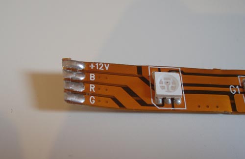
RGB LED Strip has 4 connections: +, R, G, and B. These are the 3 colors (Red, Green and Blue), which in different combinations can make all 16 million colors.
To make mixing of these colors possible, you need an RGB Controller, in addition to a power supply.
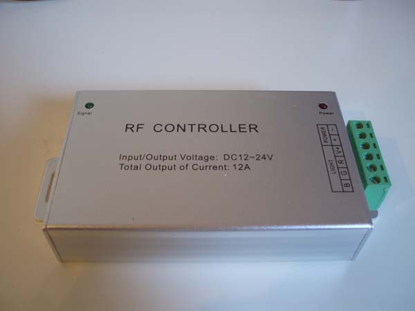
This controller includes a remote control.
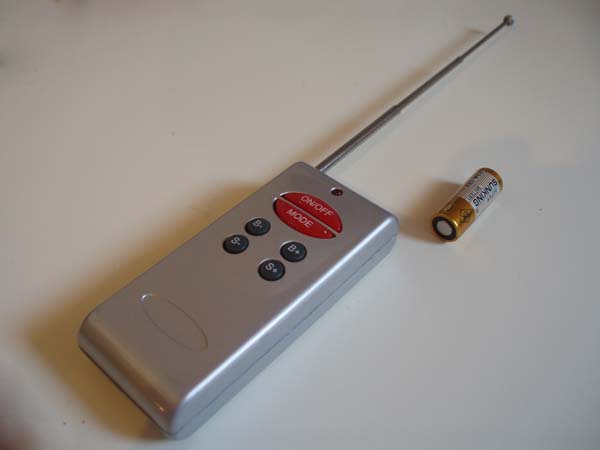
Explanation of the buttons on the remote:
[On/Off]: Turn the LED strip on or off.
[Mode]: With this button you can cycle through the different modes, including gradual color change, flashing colors, 10 static colors, and more.
[B-] en [B+] Dimfunction: Control the light intensity like with a regular dimmer.
[S-] en [S+] Speed: If applicable, these buttons control the speed with which the colors change.
2.1 How to connect?
In this explanation, we assume that you have ordered the following:
A power supply, an RGB Controller, and an RGB LED Strip.
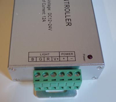
2.1.1 Connecting the RGB LED strip to the RGB controller
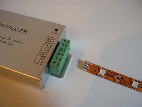
On the LED strip you can find 4 soldering points, +, R, G and B. If you look at the output of the RGB controller, you can see the same letters. The soldering points and these inputs need to be connected to each other. You will always receive some wire with your order that you can use for this. Solder this wire onto the LED strip and connect it to the correponding outputs on the RGB controller. For a soldering guide, go to Chapter 3: Soldering . It is also possible to use our soldering service.
2.1.2 Connecting the RGB controller to the power supply
On the other side of the RGB controller you will find the 12V power input. Connect the power supply here.
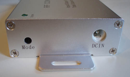
Please note: You can also connect the individual wires from the power supply to the RGB controller. Look on the other side of the RGB controller: here you will find two inputs ("Power") for the power supply.
3 Soldering
How do I solder a wire onto the LED strip?
1) Power up the soldering iron and let it warm up for +/- 5 minutes.
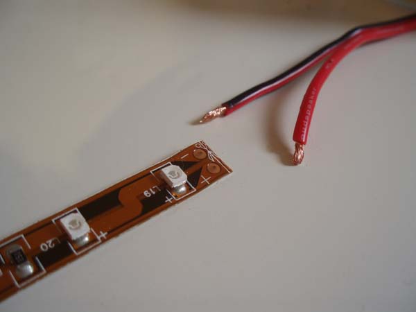
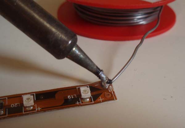
2) First, solder some tin to the soldering points on the LED strip, but do not make any connections yet. The purpose for this is to make it easier to connect the wire afterwards. Hold the soldering iron and the tin to the soldering point at the same time. This will make the tin stick to the soldering point, instead of the soldering iron.

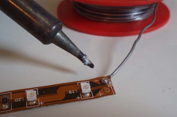
Solder tin to both of the soldering points and to the wires.
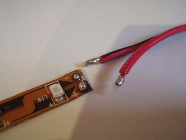
3) When this is done, put each wire on the corresponding soldering point and hold the soldering iron against it for 1-3 seconds, until it fully melts to each other. Pay attention to + and -. The + and - wires can be marked in different ways: Usually, + is red, or when both wires are black, + is marked by a grey line. It is also possible that the - wire is marked with an interrupted white line.
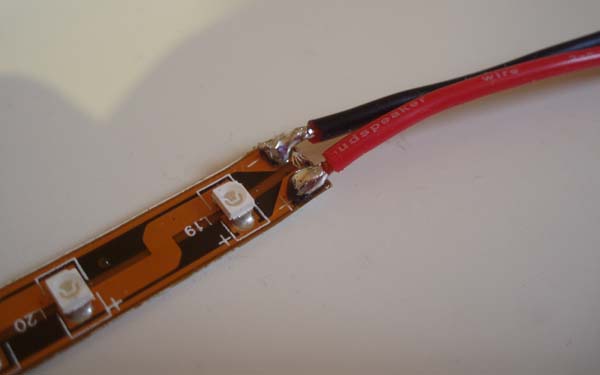
4) Ready for use.